Bringing CNC and sheet-metal manufacturability checks to free, open-source CAD
We extended an open-source FreeCAD add-on so designers can catch CNC and sheet-metal problems before a part reaches the shop, proven against 280 reference parts.
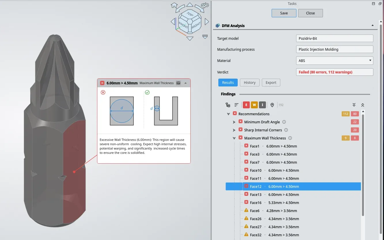
A part that looks fine on screen can be expensive, or impossible, to make. A pocket too deep for any standard cutter, a hole too close to an edge, an internal corner sharper than a tool can reach: these are design-for-manufacturing (DFM) problems. Usually they're caught by a machinist after the drawing arrives, which means a phone call, a redesign and a lost week. Commercial DFM tools catch them earlier, but they're priced for large companies. Hobbyists and small shops using free CAD have had very little.
At a glance
| Client | Open-source contribution to the FreeCAD DFM Workbench, created and maintained by Ryan Kembrey |
| Industry | Manufacturing, CAD software |
| What we built | CNC milling, turning and sheet-metal analysis for the workbench, ported from a validated C++ engine to Python |
| Where AI fits | In the build: AI-assisted engineering under a strict parity gate. The analysis itself is deterministic geometry and rules, with no model in the loop |
| Stack | Python inside FreeCAD, on the OpenCascade geometry kernel |
| Status | Open-source extension to the FreeCAD DFM Workbench |
The old way
- A designer finishes a part in FreeCAD and exports it.
- The shop opens it and finds the problems: unreachable corners, a deep narrow slot, a thread too close to a wall.
- Questions go back by email or phone, and the designer revises and re-sends.
- Each round trip costs days, and the designer learns the rule only after breaking it.
- The free tooling that existed covered plastic molding and 3D printing, not the CNC and sheet-metal work most small shops do.
What we built
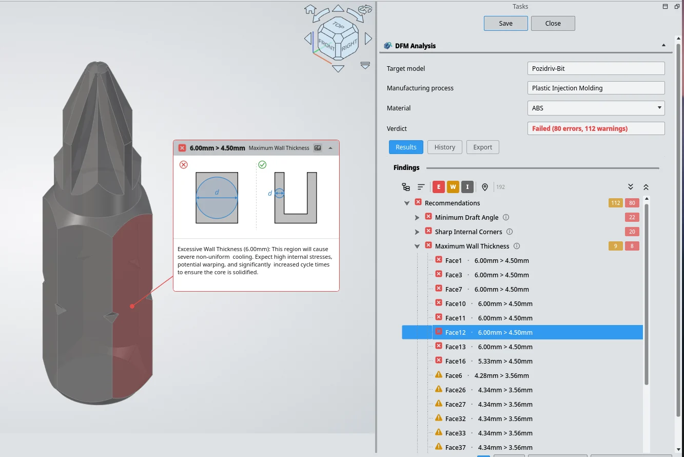
Ryan Kembrey built the DFM Workbench: a FreeCAD add-on that checks parts against 49 rules for injection molding and 3D printing. It highlights each problem on the model, explains it with a diagram of what to avoid and what to aim for, and produces PDF reports. Its philosophy is that a DFM tool should teach as well as critique.
We extended it to CNC machining and sheet metal by porting a validated engine of our own: about 40,000 lines of C++ that recognizes machining features directly from a part's raw geometry and checks them against manufacturing rules. The port brings over:
- Feature recognition. The analysis builds a map of how every face of the part meets its neighbors. Recognizers then find holes, pockets, slots, bosses, ribs, threads and freeform areas in it.
- Process classification. It decides whether a part is milled, turned, mill-turned or sheet metal, and finds the axis of rotation for turned parts.
- The rule families. Holes, threads, pockets, slots, thin features, tool access, setups, blends, bosses and ribs for machining, plus a separate set of sheet-metal rules.
All of it plugs into the workbench's existing results panel, highlighting and reports, so a FreeCAD user gets machining feedback the same way they already get molding feedback.
How the workflow changes
| Step | Before | After |
|---|---|---|
| Checking a CNC part | Export it and wait for the shop's feedback | Run the analysis in FreeCAD before exporting |
| Finding the problem | A machinist describes it by email | The faulty face is highlighted on the model, with the measured value against the limit |
| Understanding why | Tribal knowledge | Each finding explains why it matters and how to fix it |
| Sheet-metal parts | No check at all | Sheet-metal parts recognized and checked by their own rules |
| Iterating | Days per round trip | Change, re-run and compare runs in the workbench's history |
Inside the build
Under the hood
- Parity as the definition of done. A port is only correct if it gives the same answers as the original. Every change is measured against the reference engine's approved results for 280 test parts: every finding count, category, severity, recognized feature and process classification.
- The structural insight that made it tractable. Most recognizers turned out to be pure graph algorithms over the face map, with no calls into the geometry kernel. That made the port a careful transcription rather than a rewrite.
- Replaying history. The reference engine kept improving during the port, so its later changes were replayed into the Python version one commit at a time and logged in a resync ledger.
- Tested to the edges. 27 deliberately awkward "seam" variants of parts must analyze identically to their clean controls. The branch carries more than 1,400 test functions, against 191 at the point it split from the main project.
By the numbers
As of November 9, 2026:
- All 280 reference parts match the reference engine's approved results, up from 98 when the final resync began. 182 were fixed and none broke along the way.
- All 45 sheet-metal parts in the set are recognized as sheet metal, against none before the work.
- More than 1,400 test functions on the branch, against 191 where it split from the main project.
- 102 commits of ours. The base workbench is licensed LGPL-2.1-or-later, and so is our extension.
Example scenario
Example scenario (illustrative): A product designer at a five-person hardware start-up draws an aluminum bracket in FreeCAD. Before emailing it to the local machine shop, the designer runs the analysis. It highlights an internal pocket corner smaller than any standard end mill could cut, and a slot too deep for its width. The designer adds a corner radius, opens up the slot, re-runs the check, and sends a part the shop can quote straight away.
What this means for your business
Three capabilities in this project carry over directly:
- Manufacturing intelligence in the tools your team already uses. For CAD vendors, contract manufacturers and engineering teams who want design feedback before parts reach the shop.
- Migrating legacy engineering code with proof. For any company moving a trusted C++, Fortran or VBA engine to a modern language. We define "done" as matching the original's answers on your real cases, and we report the result as a number.
- Rule engines that explain themselves. For quality, compliance or inspection teams where a finding is only useful if people understand why it fired.
Second Voyage builds AI systems that are held to a standard you can check. Talk to us about yours.